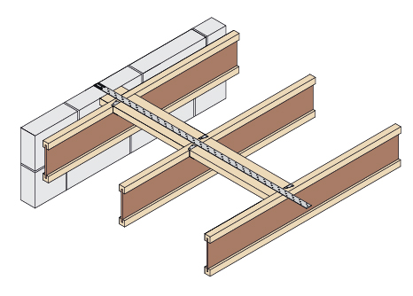
PFS surface fixed to I-Joist
- Noggins to be installed between the I-Joists with 2No UZ Clips staggered either side (Noggins to be minimum half the depth of the joists x depth of flange
- Once nailed into position a skew nail is placed in the opposite corner to secure connection
- After fitting all noggins the PFS strap can then be located tight to the block work and centred on the noggins
- The strap should be nailed with a minimum of 8No 3.4 x 35mm square twist nails evenly spaced and into at least every joist
- Strap must extend over a minimum 3No joists
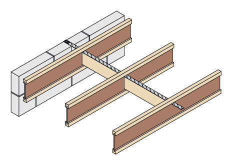
PFS through web of I-Joist
- Cut a small slot in the I-Joist web, just under the top flange
- Slide the PFS through the slots and position tight against the block work
- To provide a fixing for the PFS, noggins must be installed between the I-Joists (Noggins to be at least half the I-Joist depth, to a maximum of 150mm x minimum 38mm wide)
- Each noggin should be nailed in place through the I-Joist web
- The strap should be nailed with a minimum of 8No 3.4 x 35mm square twist nails evenly spaced into the noggins
- Strap must extend over a minimum 3No joists
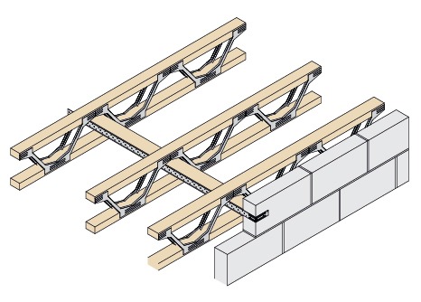
PFS through web of Open Web Joist
- Strongback to be installed as per manufacturer’s guidelines
- Position PFS tight to block work and centred on block
- The strap should be nailed with a minimum of 8No 3.4 x 35mm square twist nails evenly spaced into the noggins
- Strap must extend over a minimum 3No joists

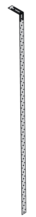
Material
Galvanised mild steel – Z275